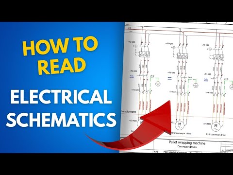
How to Read Electrical Schematics (Crash Course) | TPC Training
Summary
This webinar provides an introduction to reading electrical schematics, covering fundamental concepts, common symbol types, and differences between NEMA and IEC standards. It emphasizes the importance of understanding electrical principles, device operation, and how to interpret various diagrams like single-line, wiring, schematic, and ladder diagrams. The session highlights challenges with inconsistent symbols and outdated documentation, offering practical advice for troubleshooting and safety. It also touches upon advanced topics like IEC numbering systems and PLC ladder logic, encouraging further learning.
Key Insights
Identify and clearly mark all power sources and their overcurrent protection devices.
It is critical to know the location of all power sources for a piece of equipment, as control power may not originate from the main power panel. Overcurrent protection devices (breakers, fuses) are typically found at the source.
Symbols are the primary language for conveying information on electrical drawings.
Electrical drawings contain minimal text, making a thorough understanding of symbols essential for interpreting their meaning and using the drawing for troubleshooting.
Schematics are typically drawn in the de-energized state.
Electrical schematics are conventionally drawn as they would appear with no power applied (de-energized state). This is critical for troubleshooting, as real-world conditions with power on may present different states (e.g., a normally open contact might be closed).
In IEC schematics, odd numbers represent the source side, and even numbers the load side.
When examining IEC components, odd-numbered terminals (e.g., 1, 3, 5) are consistently associated with the power source inlet, while even-numbered terminals (e.g., 2, 4, 6) lead to the load.
Drawings are assumed de-energized unless explicitly stated otherwise.
Unless a drawing specifically states it is drawn in an energized state, it should be assumed to represent the de-energized condition, which is the standard convention.
Sections
Introduction and Poll Results
Webinar on reading electrical schematics by TPC Training with instructor Marty Redman.
Ryan Smith from TPC Training introduces the webinar on reading electrical schematics, featuring expert instructor Marty Redman. The session aims to provide practical knowledge on schematic types, common symbols, and field application.
Session recording and slide PDFs will be available post-webinar.
Attendees are informed that the session is being recorded and will be available on the TPC Training website and via email within two business days. Slide PDFs will also be provided for download.
Interactive Q&A session encouraged during the webinar.
Participants are encouraged to ask questions using the Q&A feature on their toolbar to foster interaction and discussion with the instructor.
Poll results show varied accessibility of schematics and comfort levels in reading them.
An introductory poll revealed that schematic availability and user comfort levels in reading them vary widely across facilities. Many participants are neutral, with significant portions finding them either easy or difficult to find, and similarly, comfort levels range from very comfortable to very uncomfortable.
Instructor Marty Redman has over 40 years of electrical field experience.
Marty Redman introduces himself, highlighting his 40+ years in the electrical field and 14+ years with TPC Training, underscoring his expertise in electrical schematics and the common difficulties professionals face.
Fundamentals of Electrical Schematics and Troubleshooting
Understanding basic electrical principles is crucial for effective schematic use.
A foundational understanding of how electricity works is essential for fully utilizing electrical drawings and troubleshooting effectively.
Symbols and abbreviations can vary significantly between different manufacturers and disciplines.
Symbols and abbreviations on electrical schematics are not always standardized, varying by engineering company, machine manufacturer, and even different disciplines (electrical, mechanical, plumbing, etc.), making interpretation challenging.
Knowledge of device operation is critical for accurate troubleshooting.
Understanding how individual electrical devices (motors, starters, pushbuttons, etc.) function is vital for diagnosing faults when schematics may not clearly indicate a problem.
The title block on schematics contains essential information about the machine and its history.
Title blocks on electrical drawings provide crucial information and often contain notes, updates, or revision indicators (like triangles or clouds) that highlight changes made to the drawing.
Distinguishing between NEMA and IEC standards is important for imported machinery.
Machinery from foreign countries may use IEC (International Electrotechnical Commission) standards instead of the more common US NEMA (National Electrical Manufacturers Association) standards, requiring knowledge of both to interpret drawings.
Creating site-specific drawings can aid troubleshooting when original documentation is missing.
When original schematics are unavailable, it's possible to create drawings for specific parts of machinery, especially for recurring problem areas, to simplify troubleshooting and maintenance.
Identify and clearly mark all power sources and their overcurrent protection devices.
It is critical to know the location of all power sources for a piece of equipment, as control power may not originate from the main power panel. Overcurrent protection devices (breakers, fuses) are typically found at the source.
Always identify and label power sources once identified to ensure safety and awareness.
When power sources or their associated disconnects are found, they must be clearly identified and labeled so that all personnel are aware of their function and location, not just the person who found them.
Loads are devices that perform work, such as motors or indicator lights.
A 'load' in an electrical circuit is defined as a device that performs work, ranging from simple components like pilot lights to complex machinery like three-phase motors.
Correctly sized conductors (wires) are essential for circuit safety and function.
Understanding current flow and ensuring conductors (wires) are properly sized according to codes like the National Electrical Code (NEC) is crucial for safe and effective circuit operation, especially for motor loads.
Wire sizes are often not explicitly shown on control drawings but are detailed elsewhere.
Control drawings typically show the path of current flow using lines, but do not usually specify wire sizes. This information is generally found on separate drawings or documentation.
Types of Electrical Drawings
Single-line diagrams show main power distribution using a single line per path.
Single-line diagrams illustrate the main electrical distribution within a facility, using one line to represent power paths instead of three. They depict components like disconnects and fuses and often include a numbering scheme to trace power back to the source.
Outdated single-line diagrams pose significant safety risks.
Failure to keep single-line diagrams updated with facility modifications creates safety hazards, as personnel may not know which breakers or circuits control specific equipment, potentially leading to accidents. OSHA regulations emphasize the importance of updated diagrams.
Wiring diagrams show the physical location of terminations and connections.
Wiring diagrams detail the physical layout of connections and terminations for components within a system, varying in detail depending on the manufacturer or engineering firm.
Schematic diagrams illustrate electrical operation and component interconnections.
Schematic diagrams focus on the electrical operation of a system, showing how components like relays are interconnected to achieve a specific function, rather than their physical location.
Ladder diagrams are standard for industrial control systems, showing current paths.
Ladder diagrams are widely used for industrial controls because they clearly depict the path current must take to energize a load, regardless of the physical distance between components. They are read top-to-bottom, left-to-right.
Floor plans and site plans provide physical location and layout information.
Floor plans indicate the location of components like motor control centers or panels within a facility, while site plans show the overall property layout, including power entry points and transformer locations.
Lack of updated documentation leads to significant maintenance and safety challenges.
When drawings are not kept up-to-date with modifications, maintenance becomes difficult, and safety is compromised as the presented information does not reflect the actual installation. Maintaining documentation requires dedicated effort.
Proactive study of schematics during downtime improves readiness for critical situations.
It is beneficial to review and study schematics, including understanding their numbering schemes and symbols, during periods of low activity or break times, rather than only when a critical failure occurs.
Understanding Electrical Symbols
Electrical symbols are not universally standardized; variations exist.
There is a lack of universal standardization for electrical symbols, with different companies and disciplines using their own conventions ('better mousetrap' analogy). This has improved somewhat since the 1990s due to CAD software.
Legend sheets are crucial for understanding non-standard symbols on a drawing.
Most drawings, especially when new, include a legend sheet that defines all symbols used in that specific document. If this sheet is missing or unavailable, interpreting symbols becomes significantly more difficult.
Electronic drawings obtained from manufacturers are more likely to be accurate.
Since the widespread adoption of CAD, obtaining updated electronic drawings from equipment manufacturers can provide a reliable, though possibly slightly modified, representation of the system.
Symbols are the primary language for conveying information on electrical drawings.
Electrical drawings contain minimal text, making a thorough understanding of symbols essential for interpreting their meaning and using the drawing for troubleshooting.
Power and control symbols are often separated onto different drawing sets.
Depending on machine complexity, power circuit symbols and control circuit symbols may be presented on separate sets of drawings, linked by a numbering system.
Fused disconnect switches may include auxiliary contacts to indicate status.
Symbols for fused disconnect switches can include auxiliary contacts, which provide information about the switch's state (open/closed) for control circuits, though they don't confirm fuse integrity.
Non-fused disconnect switches can be used locally with upstream overcurrent protection.
Non-fused disconnect switches, often placed near motors, rely on upstream overcurrent protection. They also feature auxiliary contacts for status indication, which can be reflected on HMI systems.
Contactors are used to switch loads, like for lighting or motor control.
A three-phase contactor symbol represents a device capable of handling significant current, used in various applications including motor control circuits and in front of variable frequency drives (VFDs).
Overload relays protect motors from excessive current, with details on power prints.
Overload relay symbols on power prints indicate motor protection against overcurrent. Details like type and current rating are often specified on these prints.
Normally Open (NO) pushbuttons are momentary switches for initiating actions.
A normally open (NO) pushbutton is a momentary switch that completes a circuit only when pressed. It's commonly used as a motor 'start' button.
Normally Closed (NC) pushbuttons are momentary switches for stopping actions.
A normally closed (NC) pushbutton is a momentary switch that breaks a circuit when pressed. It's typically used as a motor 'stop' button or for emergency stops (often with mushroom heads).
Distinguish between an E-stop and a normal stop button for proper shutdown.
It's crucial to differentiate between an emergency stop (E-stop) button, which halts all operations immediately, and a normal stop button, which allows for a controlled shutdown sequence.
Limit switches use mechanical force to change their contact state.
Limit switches have contacts that are either normally open (NO) or normally closed (NC). They require physical actuation (e.g., by a door or arm) to change state. Gravity often influences the default state.
Be cautious with limit switch symbols that appear reversed due to actuation.
Some limit switch symbols can be confusing (e.g., appearing normally closed but held open by actuation). It's vital to correctly observe the symbol's notation to avoid troubleshooting errors.
Float switches activate based on liquid levels in tanks.
Float switches are used in applications involving liquids, such as tanks, to detect level changes. They can have normally open or normally closed contacts.
Pilot lights use a lens to indicate status, with color specified by a letter.
Pilot lights are load indicators, often drawn as a circle with a letter inside specifying the lens color (e.g., 'G' for green).
Control relay coils (CR) are fundamental components in control circuits.
A control relay coil, often symbolized by a circle with 'CR' (or 'R') inside, is a key element in ladder diagrams that, when energized, changes the state of its associated contacts.
Solenoids are used to actuate valves and cylinders.
Solenoid symbols represent actuators used in pneumatic or hydraulic systems to control valves, cylinders, and other mechanical movements.
Relay contacts (NO/NC) change state when the coil is energized.
Symbols for relay contacts show normally open (NO) or normally closed (NC) configurations. These contacts change their state (open to closed, or closed to open) when the associated relay coil is energized.
Schematics are typically drawn in the de-energized state.
Electrical schematics are conventionally drawn as they would appear with no power applied (de-energized state). This is critical for troubleshooting, as real-world conditions with power on may present different states (e.g., a normally open contact might be closed).
Ladder Diagrams and Numbering Systems
Ladder diagrams use 'rails' and 'rungs' to illustrate control circuit paths.
Ladder diagrams are structured with vertical 'rails' on each side and horizontal 'rungs' connecting them, visually representing the path for current flow in a control circuit.
Ladder diagrams are read sequentially from top to bottom, left to right.
The operational sequence of a machine is followed by reading a ladder diagram from top to bottom, with the current path typically traced from left to right across the rungs.
Rung numbers on the left side of a ladder diagram facilitate location.
Red numbers on the left side of a ladder diagram indicate rung numbers, serving as locators to help find specific circuits or components within a potentially large drawing.
Numbers on the right side of a ladder diagram identify component contacts.
Numbers on the right side of a ladder diagram are associated with a specific component (e.g., a motor starter coil) and indicate the rung numbers where its corresponding contacts (normally open or normally closed) can be found.
Control circuit states (energized/de-energized) determine component behavior.
Understanding whether a machine should have indicator lights or other signals when powered on is crucial for troubleshooting. Differences from the expected state can indicate issues.
Understanding IEC Schematics and Numbering
European equipment often uses IEC standards, but not always exclusively.
While European machinery typically adheres to IEC standards, equipment manufactured in the US but using European components may not strictly follow IEC wiring conventions.
IEC schematics are read left-to-right, top-to-bottom, with a structured numbering system.
IEC drawings employ a systematic numbering convention that includes print group, page number, and component identifiers, aiding in navigation across extensive documentation sets.
IEC numbering indicates print group, page number, and component association.
In IEC drawings, a number like 'A7-002 K11' signifies the print group (A), page number (002), and component identifier (K11 for a contactor/relay). This system helps link related components across different pages or sections.
IEC uses 'spaces' or 'rungs' similar to NEMA ladder diagrams.
IEC ladder diagrams also use 'spaces' (analogous to rungs) where components reside, and these spaces are numbered sequentially to denote their position within the logic.
IEC contactors are identified by single-digit numbers; relays by double-digit numbers.
Single-digit numbers typically denote IEC contactors, while double-digit numbers identify relays. This distinction helps differentiate components based on their current handling capacity.
In IEC schematics, odd numbers represent the source side, and even numbers the load side.
When examining IEC components, odd-numbered terminals (e.g., 1, 3, 5) are consistently associated with the power source inlet, while even-numbered terminals (e.g., 2, 4, 6) lead to the load.
IEC wiring uses specific numbers to denote contact types (NO/NC).
IEC systems use number pairs to indicate switch states: 1-2 for normally closed (NC) and 3-4 for normally open (NO). This applies to pushbuttons, limit switches, and relay contacts, replacing abbreviations like 'NO' or 'NC'.
IEC contactors have odd/even numbered power contacts and A1/A2 for coil.
IEC contactors have odd-numbered power contacts for the source and even-numbered for the load. The coil terminals are consistently A1 (source) and A2 (neutral/ground). Auxiliary contacts typically have double-digit numbers.
IEC distinguishes between a contactor and a motor starter based on overload integration.
An IEC motor starter signifies a combined contactor and overload relay. If only a contactor is present, overloads are often found in a separate manual starter unit.
IEC relay contacts are numbered sequentially (e.g., 13, 21, 31) to identify individual contacts.
Double-digit numbers on IEC relays indicate specific contacts. The first digit refers to the contact number on the relay (e.g., 1st, 2nd), and the subsequent digits indicate its state (e.g., 3-4 for NO, 1-2 for NC).
IEC symbols for components like pushbuttons and limit switches use number logic for state.
IEC employs number pairs (e.g., 3-4 for NO, 1-2 for NC) on components like pushbuttons, limit switches, and foot switches to denote their contact state, providing a standardized representation.
Special purpose contacts in IEC are often related to overloads or manual starters.
In IEC drawings, contacts numbered 5-6 typically denote special purpose contacts, often associated with overload conditions or manual motor starters.
IEC pilot lights use specific symbols and A1/A2 for coil connections.
IEC pilot lights have distinct symbols, often with an 'X' or similar indicator, and are connected via A1 (source) and A2 (neutral/ground) terminals, similar to relay coils.
IEC ladder diagrams show component associations clearly.
An IEC ladder diagram example demonstrates how overload contacts, stop buttons, start buttons, and auxiliary contacts are linked to specific components and shown in relation to the main coil, with associated contact details often provided below the diagram.
Q&A and Further Learning
Distinction between float switches and limit switches.
A float switch is a type of switch activated by liquid level, typically located in tanks. A limit switch is mechanically actuated by physical contact with an object (like a door or arm) and is not used in liquids.
Industry standards for symbols vary globally; NEMA and IEC are primary.
While NEMA and IEC are the main standards, other countries may have variations. The quality of prints often correlates with the investment in engineering. US-based wiring with European parts may not strictly follow IEC.
Schematics focus on current flow path, not electron vs. hole flow theory.
For practical troubleshooting, schematics focus on the path current takes to energize devices, regardless of the theoretical debate between electron flow and hole flow.
Special purpose contacts in IEC usually relate to overloads integrated into manual starters.
Special purpose contacts (e.g., 5-6) in IEC are often associated with overloads integrated within manual motor starters, differentiating them from standard relay or contactor contacts.
Learning PLC ladder logic is valuable for troubleshooting older equipment.
PLC programming using ladder logic is still relevant for troubleshooting machines programmed in the 2000s and earlier. TPC Training offers courses covering this topic.
Limit switches can function as tool interlocks.
Yes, a limit switch can be used as a tool interlock to ensure a tool or component is in the correct position before operation begins, using either normally open or normally closed contacts.
Drawings are assumed de-energized unless explicitly stated otherwise.
Unless a drawing specifically states it is drawn in an energized state, it should be assumed to represent the de-energized condition, which is the standard convention.
CAD software aids in managing and numbering schematic elements.
Computer-Aided Design (CAD) software is beneficial for managing drawings and implementing numbering systems, especially for large or complex machinery where consistent identification of wires and components is critical.
TPC Training offers comprehensive schematics classes.
Due to the complexity and breadth of electrical schematics, a full two-day class is recommended for in-depth learning, which TPC Training provides.
Contact TPC Training for more information and assistance.
Contact information (phone number 847-808-4000, sales@tpctraining.com) is provided for those seeking further information or assistance with electrical schematics and training.
Ask a Question
*Uses 1 Wisdom coin from your coin balance